Category Archives: Equipment Teardowns

Strong 2.5kW Xenon lamp ballast teardown

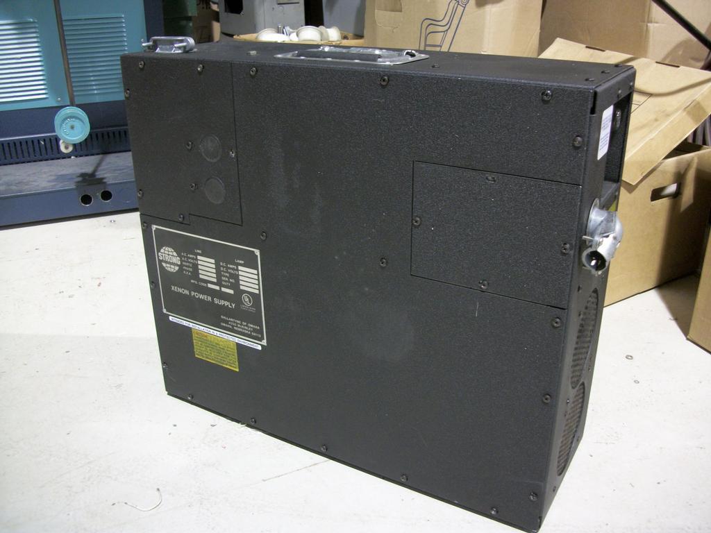
This is a Strong model 62-80005 Xenon short arc lamp ballast, out of the now demolished Station Square cinemas at Metrotown. This drove lamps up to 2.5kW for the small auditoriums in the cinema. The large auditoriums ran up to 6kW lamps.

Here’s the User manual
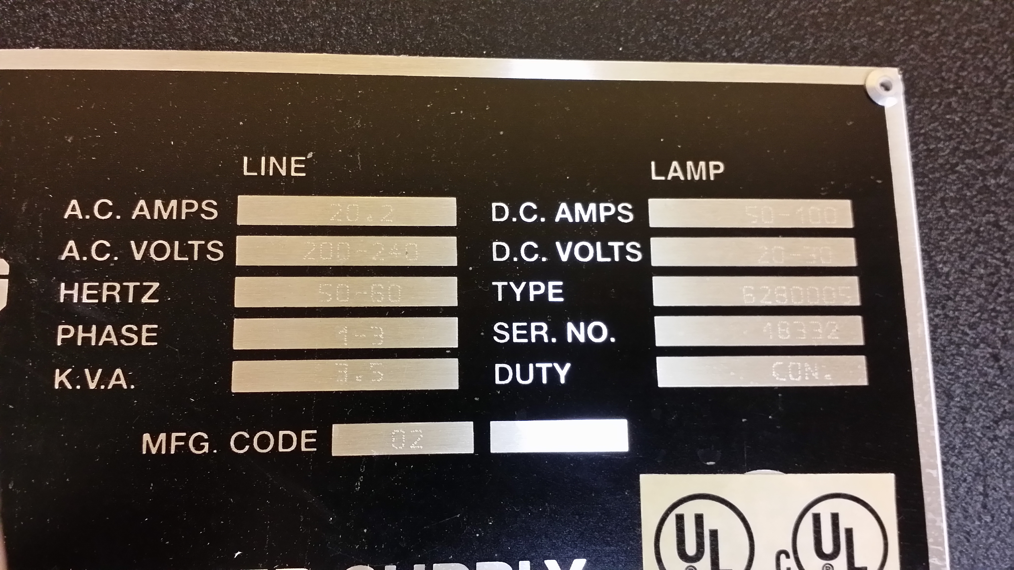
Strong Xenon Power Supply 1-3 Phase_full

Ratings are
200-240V 1-3 phase 20.2A input
20-30VDC 50-100A output

20141029_010123

20141029_00493720141029_004814We were greeted with the lamp current control pot jammed in the output junction box by the installers.

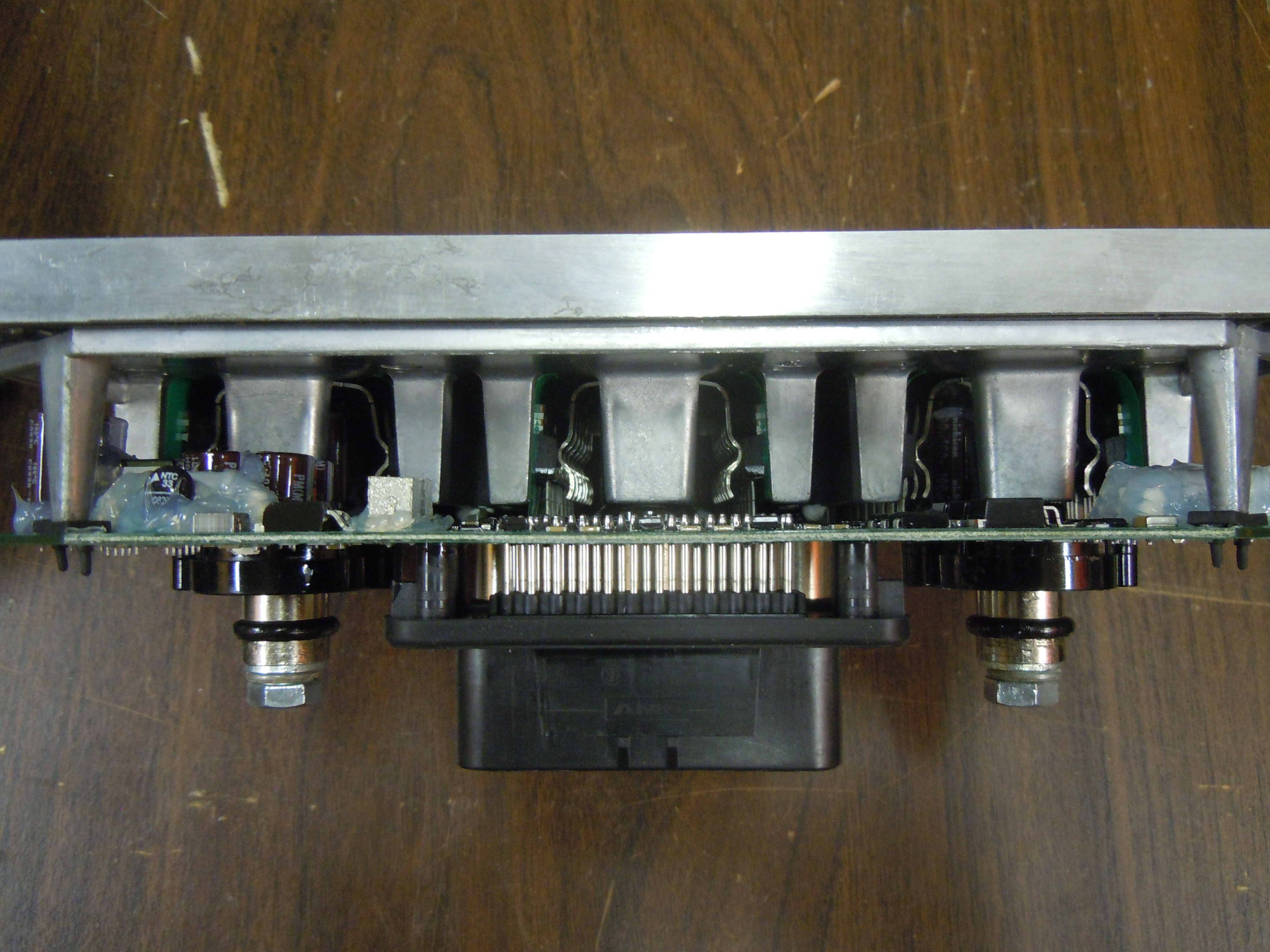
This ballast dates from 1998, and appears to be an older design. As expected, it’s built very well, with the entire chassis being aluminum.

20141029_010014_fixed
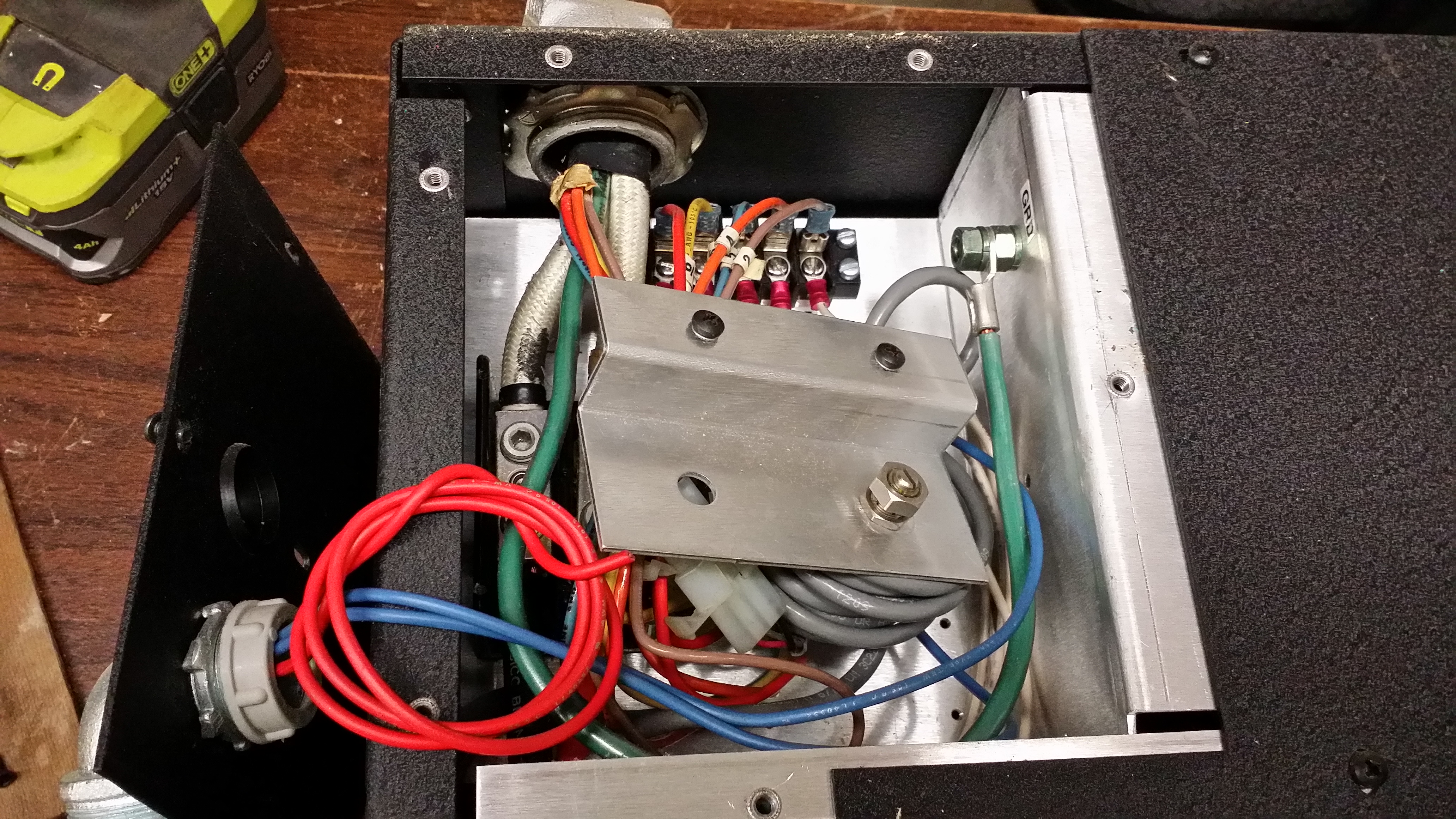
In the above photo, 3-phase input connections are on the top right, bus capacitor precharge contactor top middle, DC output top left. On the bottom right is the EMI filter and main bus capacitor (6800uF 350V), and the bottom left contains the actual switching power supply unit.

20141029_010034
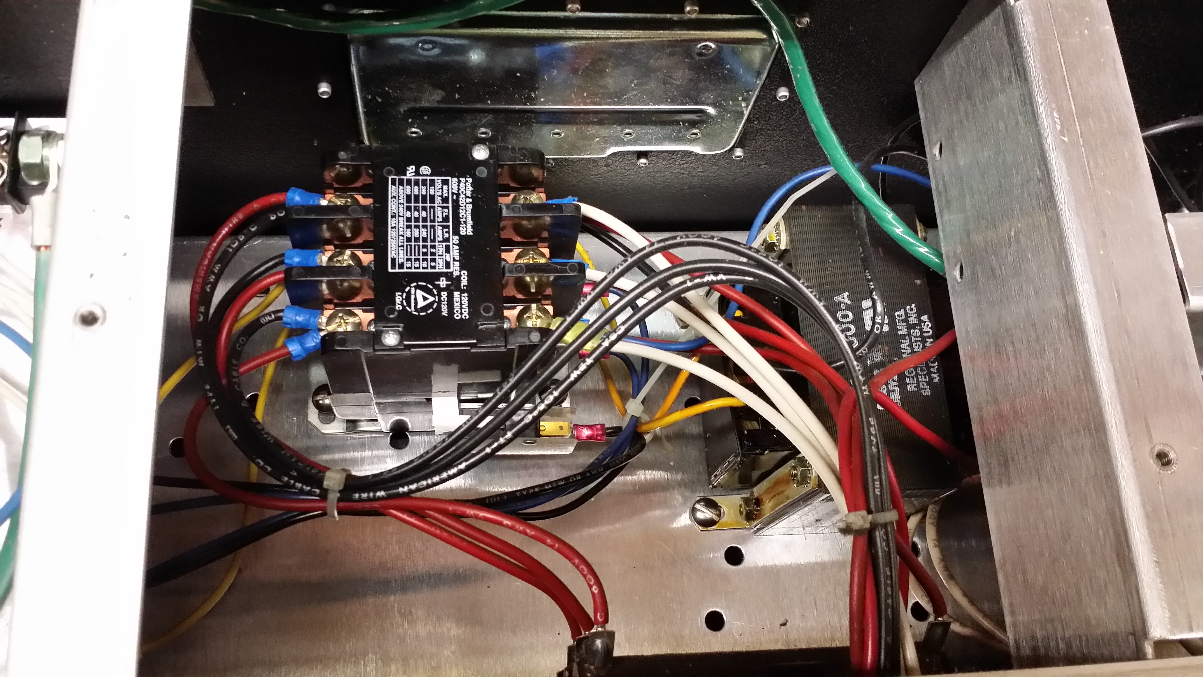
Close up of the contactor and 240-120V transformer used to run auxiliary systems in the projector. Also contains the three 5ohm 50W bus precharge resistors, which the contactor shorts out once the bus cap is charged. This avoids blowing the input breaker when turning on the power and charging up the capacitor.

20141029_010028
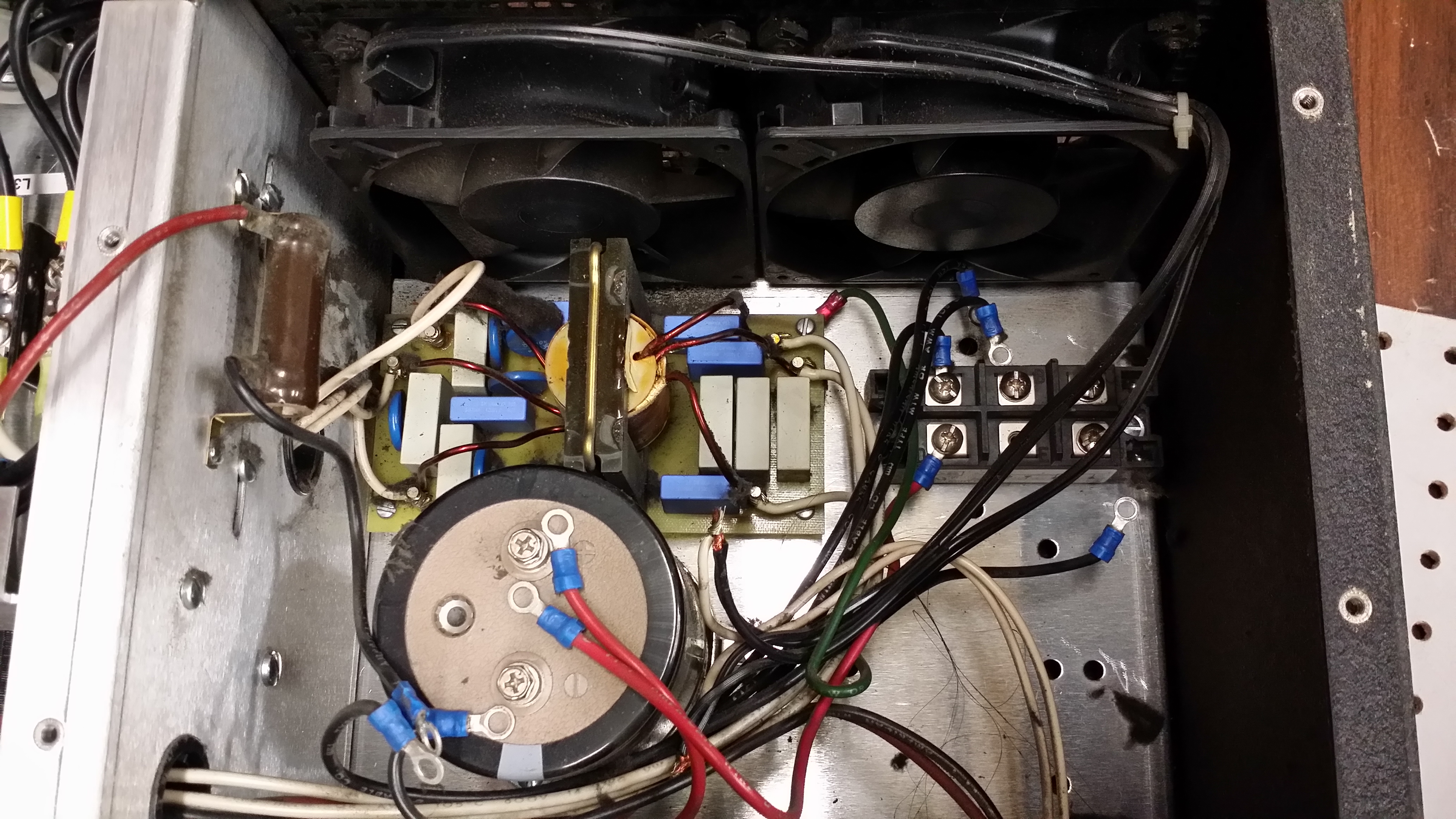
EMI filter, DC bus cap and input rectifier. Bus cap bleeder resistor also visible on the left.
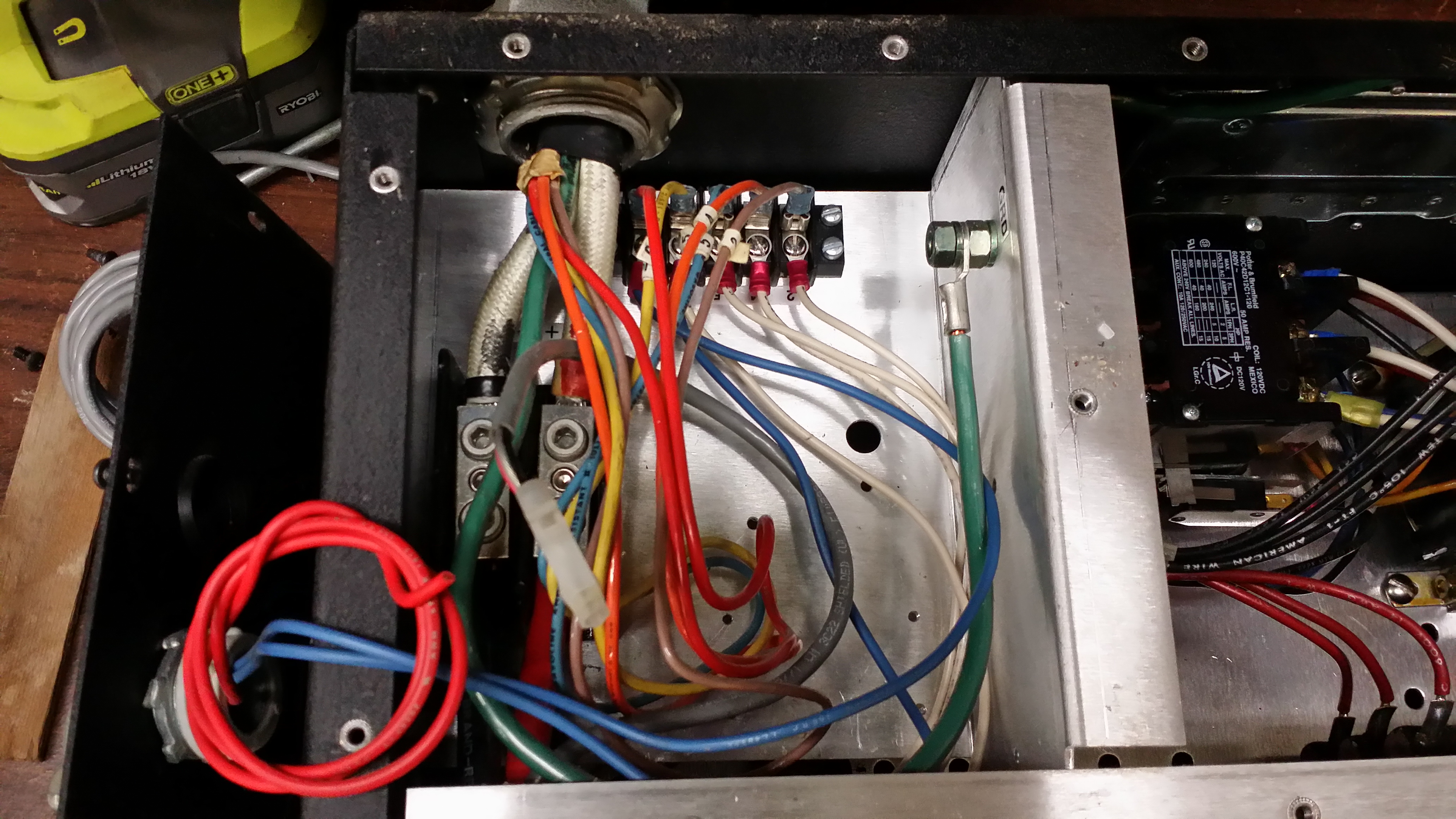
20141029_010039
DC Output terminals

20141029_010022
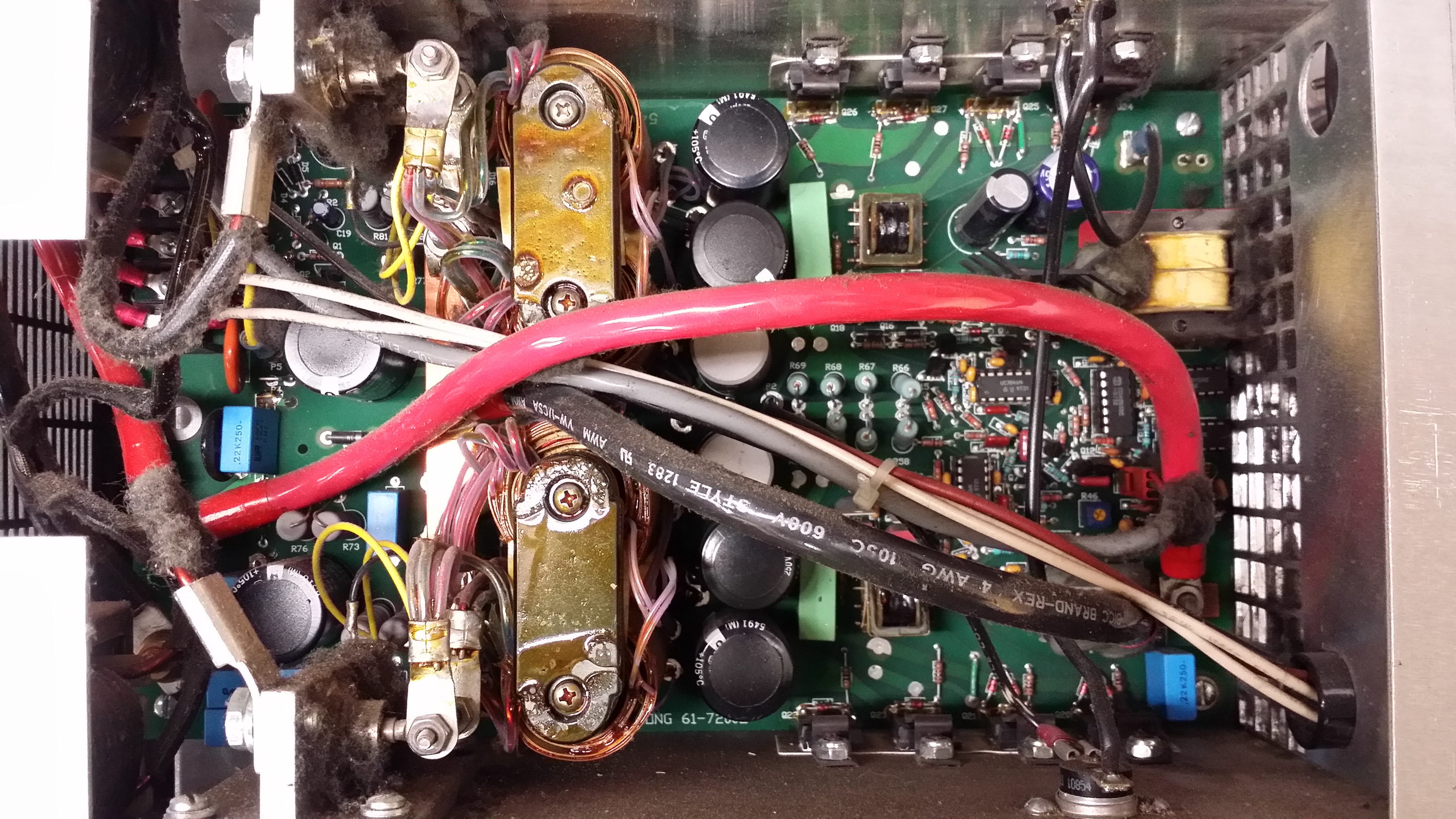
Switching power supply

Schematic
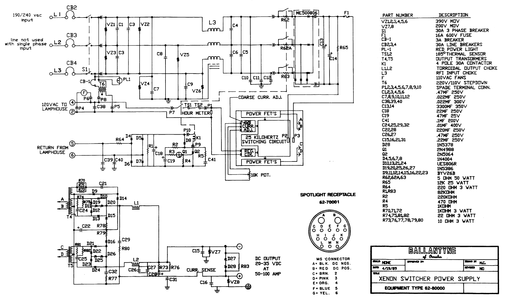
Schematic from manual. It’s basically two separate paralleled full bridge converters with full wave centertapped output rectification.

20141029_030844

20141029_030929
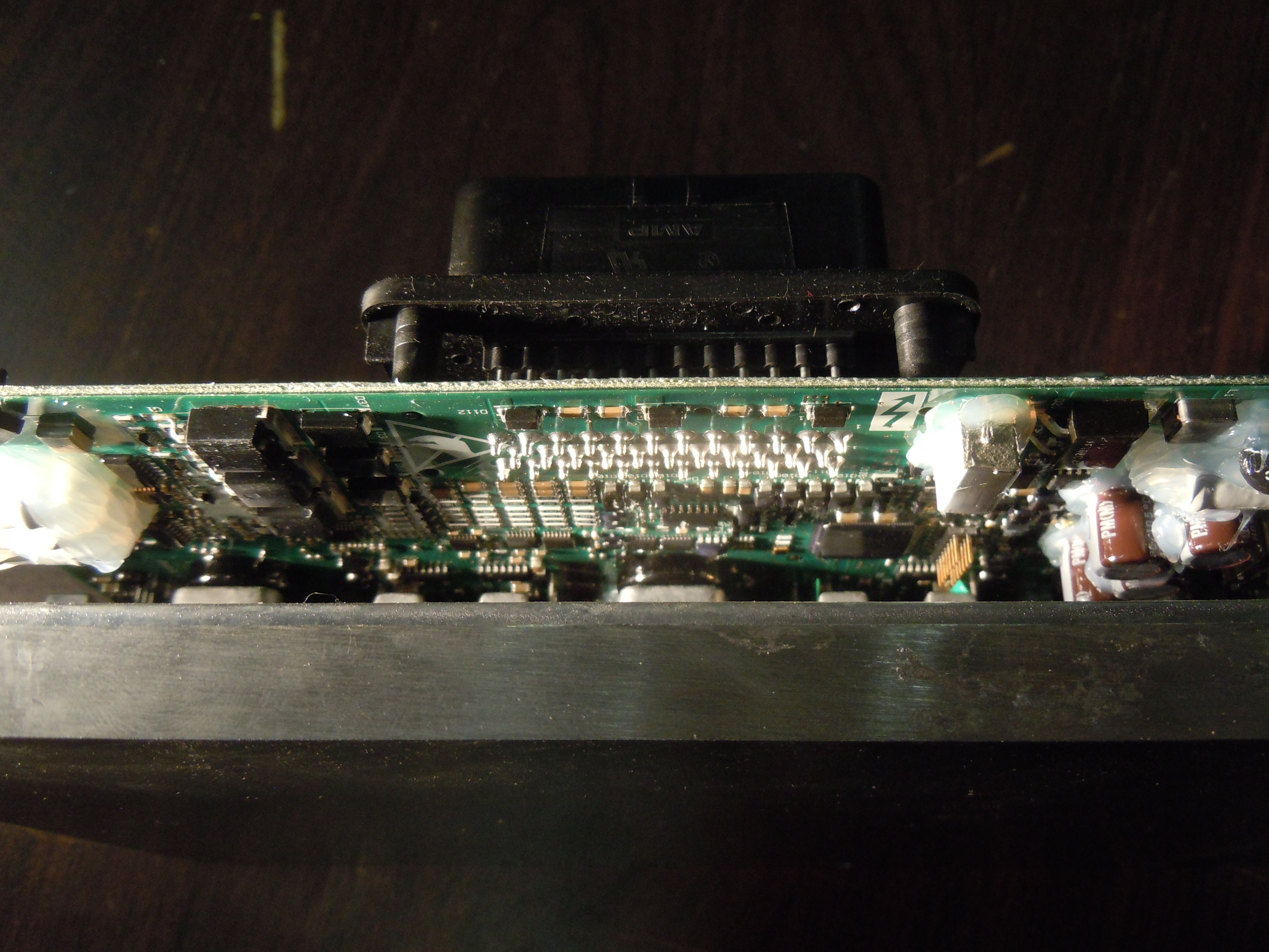
Control section has a very “organic” layout, the designer must have really been cramming to get everything to fit.

20141029_030916

20141029_030903

20141029_031014
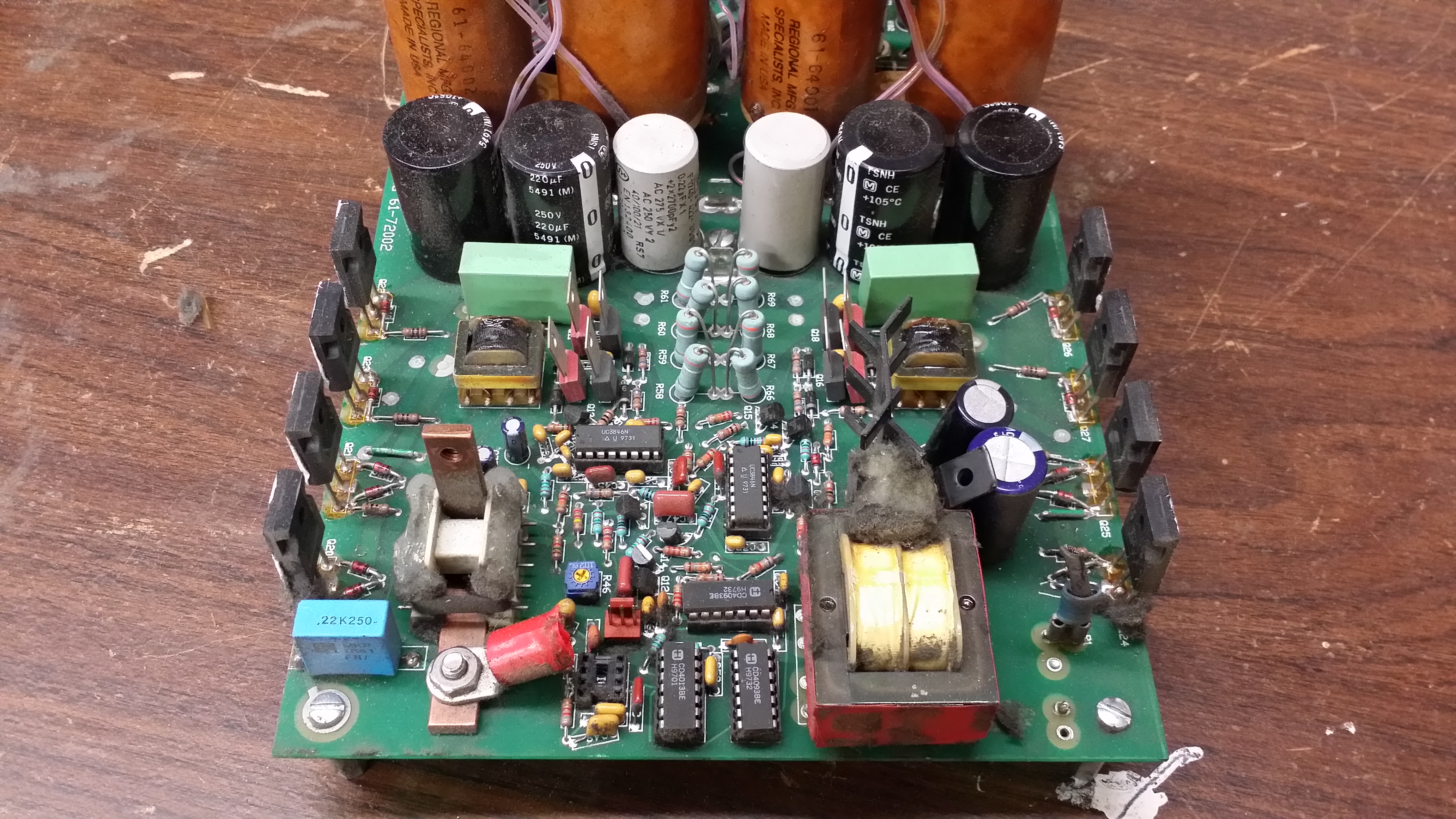
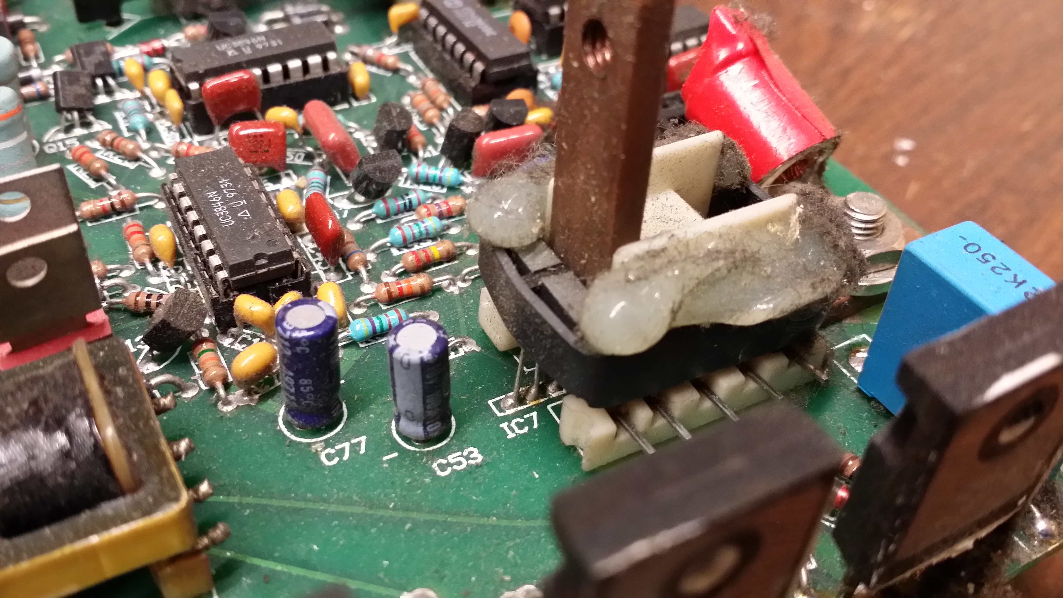
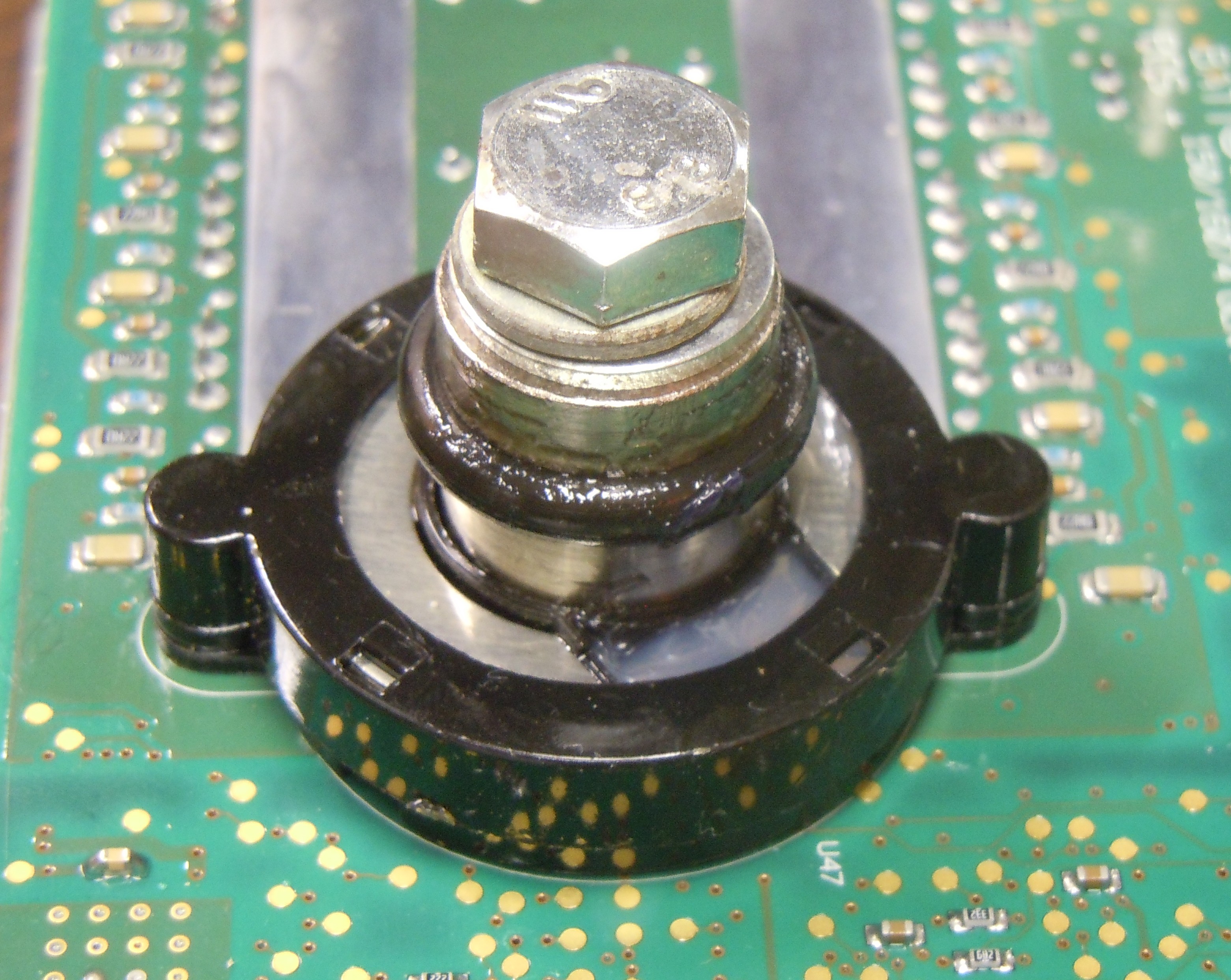
The output current sensor is clever, just a standard ferrite core with a hall sensor stuck in the core gap. Probably much cheaper than the commercial versions of these sensors, especially at this current rating.

20141029_030943
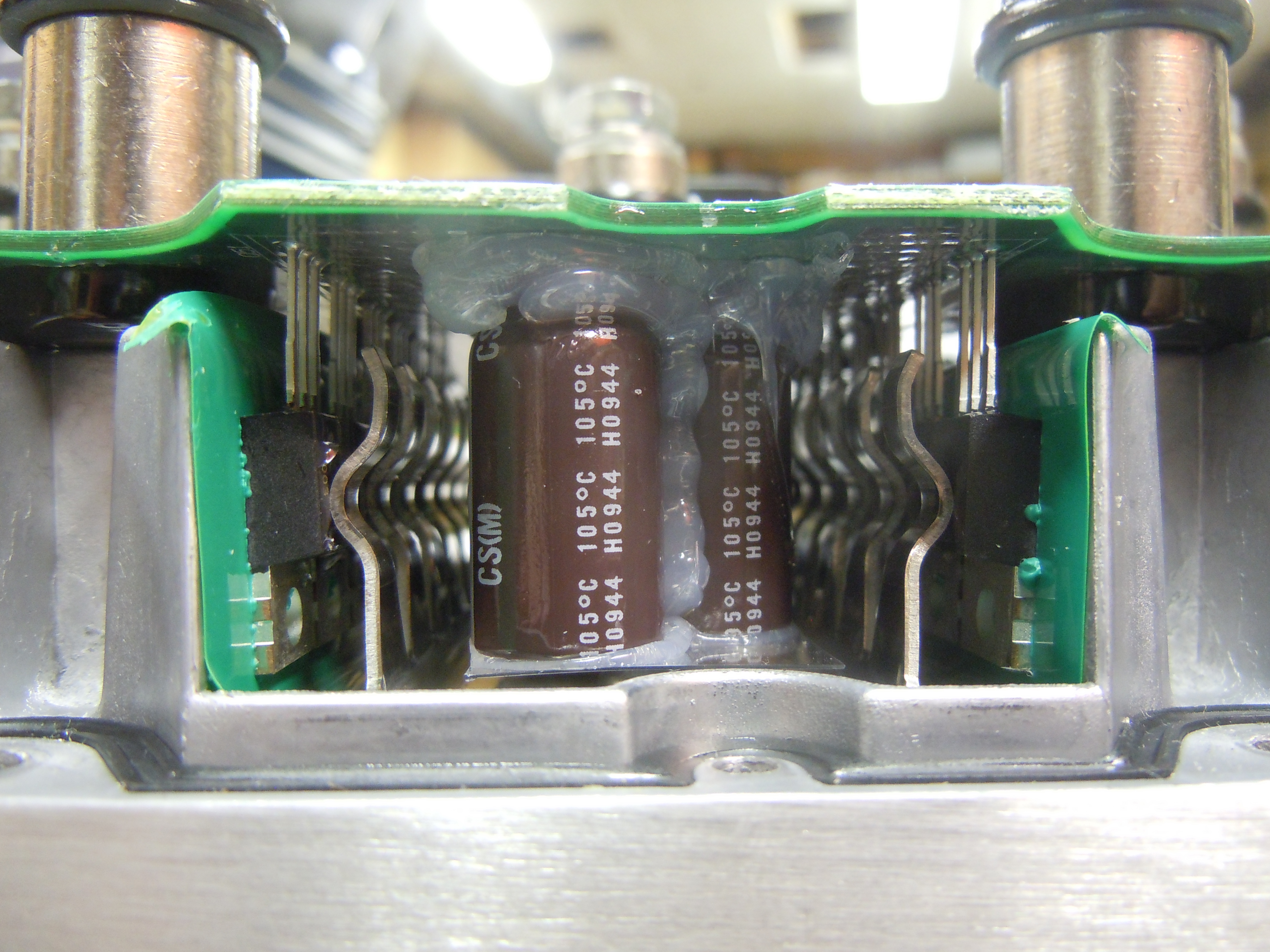
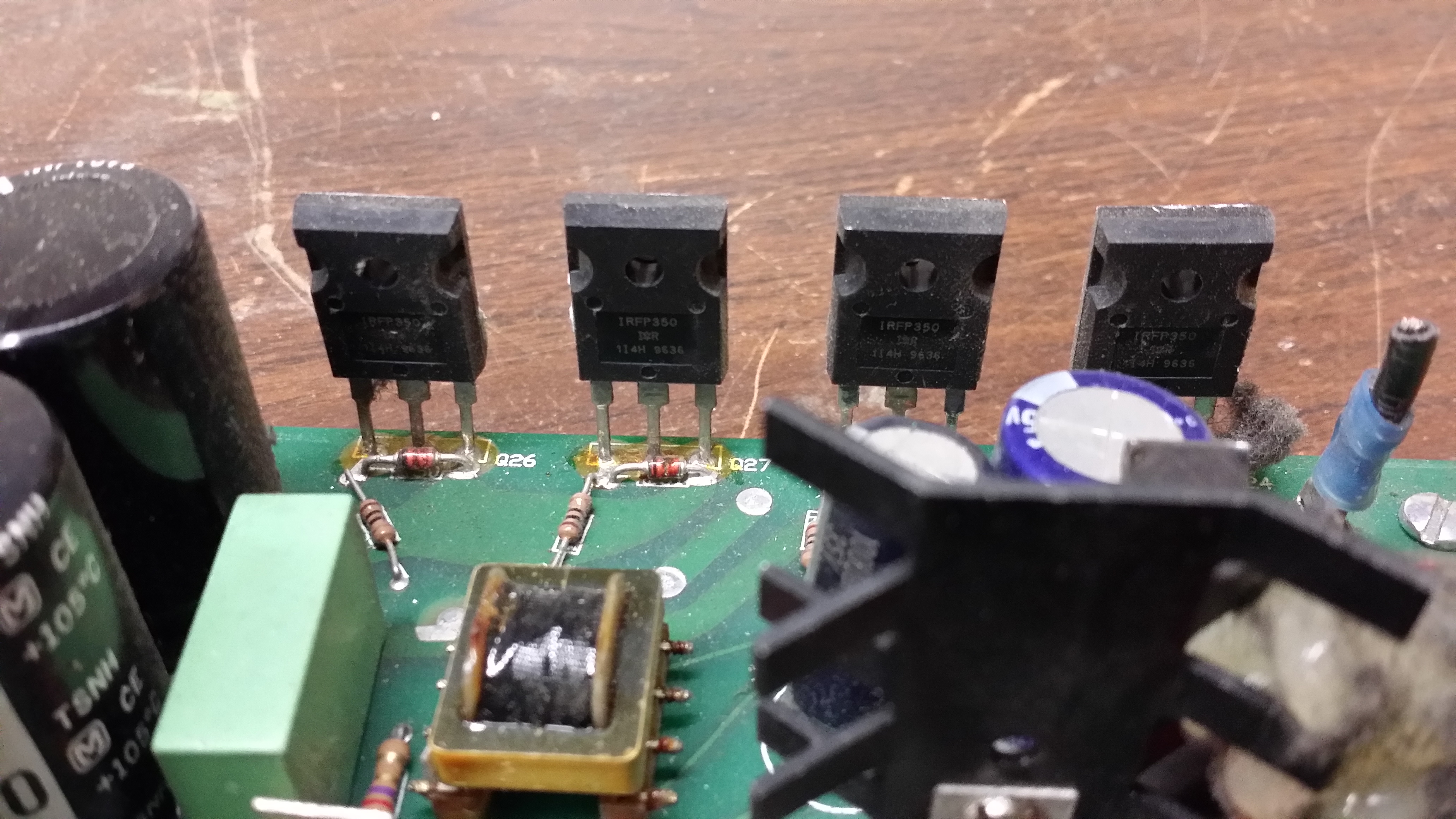
IGBTs are IRFP350 rated 400V 16A

20141029_031510
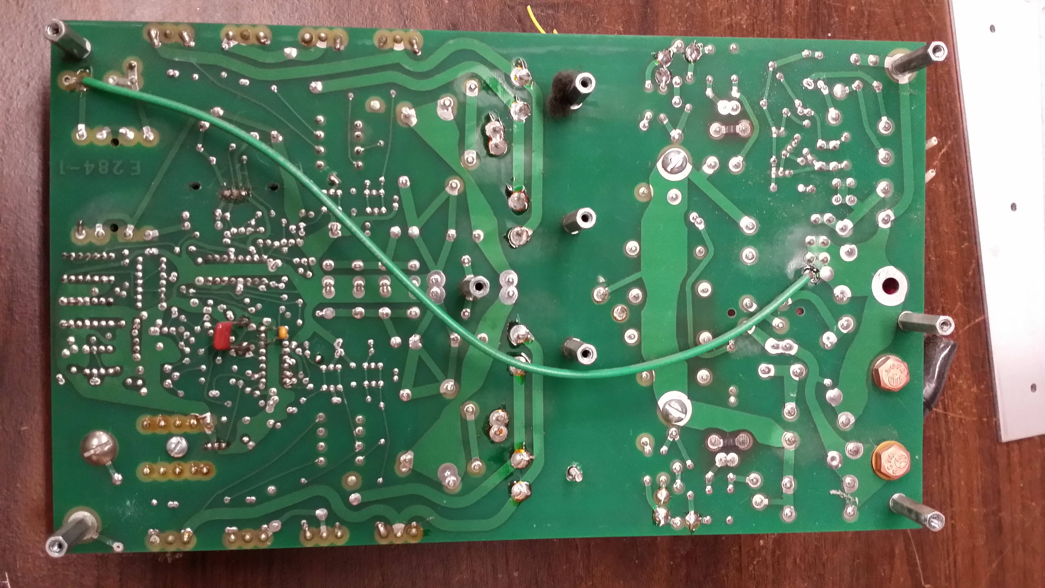
Not too bad – only a few bodge wires/components. I figure the green wire was for some safety ground purpose and and not EMI.

20141029_031545
A couple of burnt up connections on some resistors

20141029_01020320141029_031051
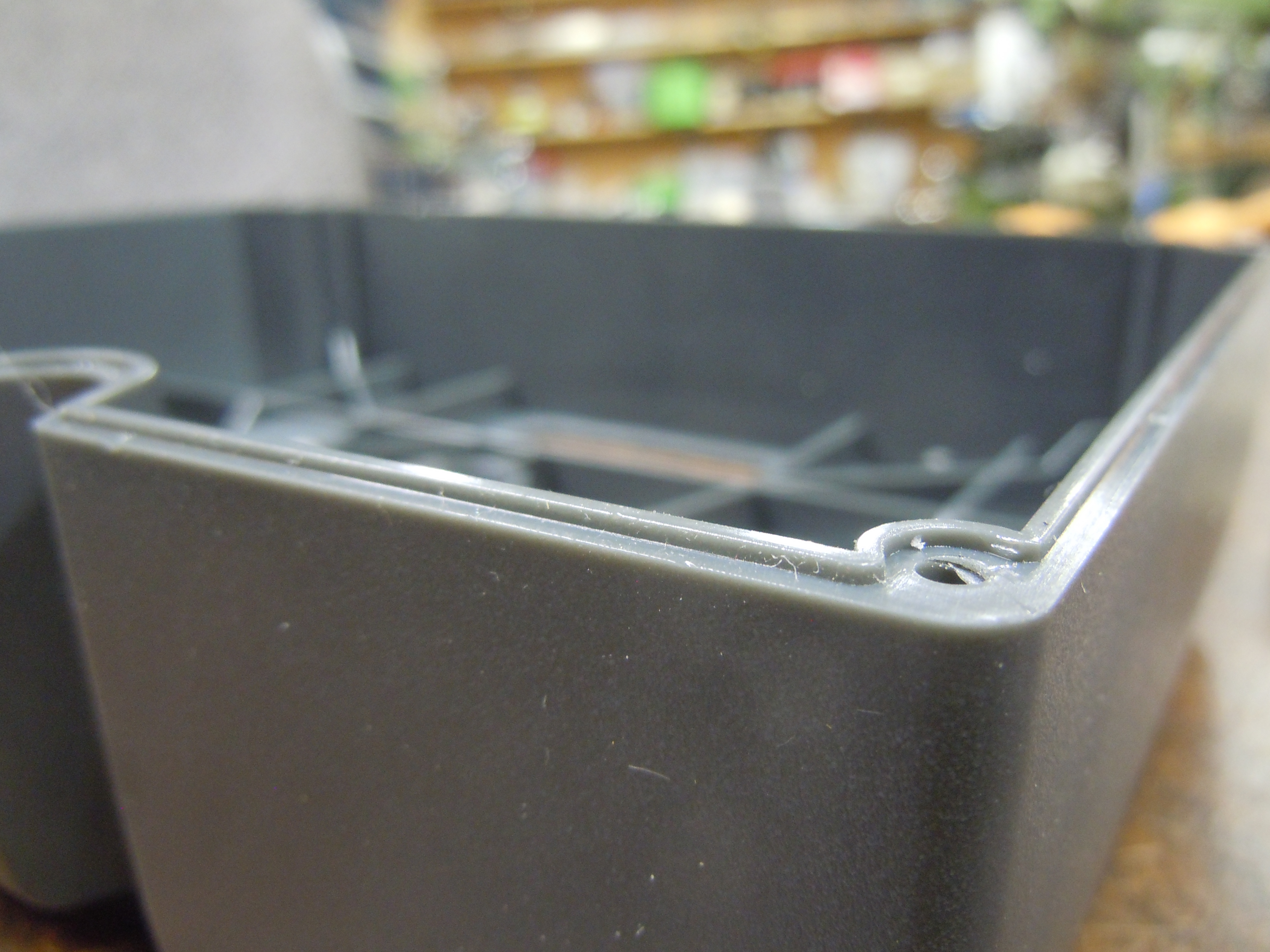
The EMI Filter has an absolutely dreadful layout, with long ground traces connecting to the Y caps.

20141029_031829
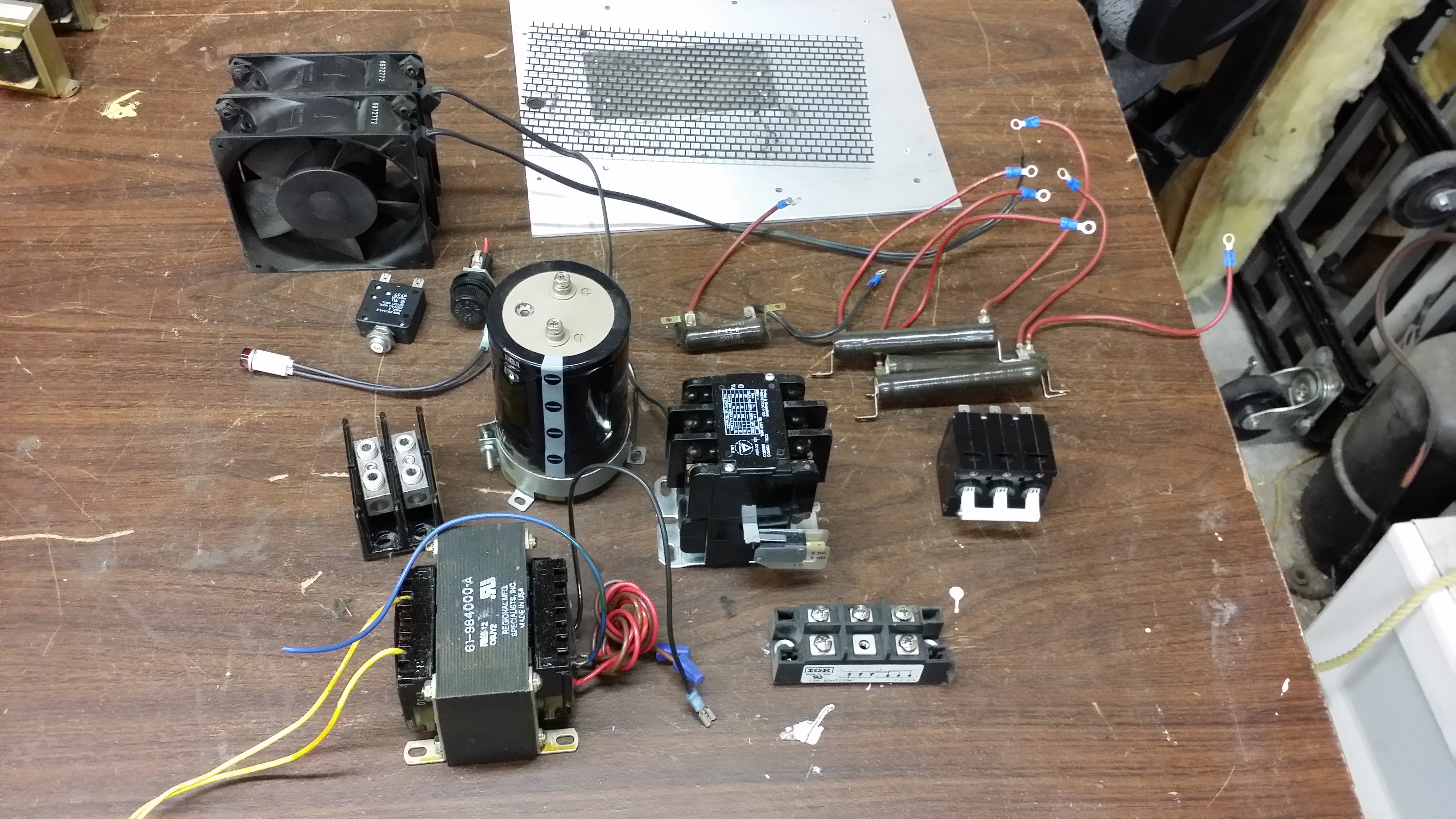
And all the goodies left over at the end!

Want more high current ballast goodness? Check out the video teardown of the 7kW version of this ballast. Completely different architecture!


Sevcon Gen4 AC motor controller teardown

Here’s a look inside a Sevcon Generation 4 AC motor controller. This particular one is the 80V 350A model, sourced for the ArcWolf racing go-kart. Two were purchased from an eBay seller in located in Korea for US$720 total including shipping.

Imgur album of all teardown photos

The controller is waterproof with a plastic shell over an aluminum base plate. Terminals protrude through the top.
DSCN4758

With the screws removed, the top comes off with prying.
DSCN4759

DSCN4763

Just one big board. Surprisingly there are no bus bars, the 350A connections go directly to the PCB! The three half bridges are clearly visible. Each leg uses seven IPP075N15N3 G 150V 7.5mOhm FETs.

The PCB is at least four layer. The top and bottom layers both carry the current from the FETs to the 3 phase outputs, with the DC bus running on inner layers. The number of inner layers is not known.
DSCN4765

The FETs are clamped to the heatsink by spring clamps. These must be held open with a special jig during assembly while the top board is inserted.
DSCN4778

A green thermal interface material couples heat to the heatsink. The material is basically a think Kapton sheet with a phase change material that melts at high temperature. I recall using this material in an AC inverter I built years ago because it was the highest performance economical material available. It likely still is to this day.

The bus capacitors are Nichicon 160V 100uF with 8 per leg (2400uF total). The capacitors and other weak components are secured with silicone to stop them from breaking off due to vibration.
DSCN4789

Current sensing is accomplished with hall effect current sensors. These are simply a slotted toroidal magnetic core around the power conductor.  The slot concentrates the magnetic field, allowing a hall effect sensor in the slot to sense the magnetic flux which is proportional to the current. The gap / hall sensor is under the clear silicone.
DSCN4768

The magnetic laminations are visible. For high current applications ferrite may saturate, so iron laminations are used instead.
DSCN4770

Terminals are sealed with o-rings. Grease is applied presumably to ease assembly and to improve sealing.
DSCN4772

The logic section of the board is hard to see without removing the entire board. There’s not too much here, a large amount of IO protection near the connector, a switching power supply to the right, and what I believe are contactor drivers on the left.

The main micro is a TMS320F2811 32-bit 150MHz device, quite powerful!
DSCN4783

Heatsink temperature is sensed by two thermistors mounted to the main PCB and inserted into holes in the main heatsink. There are no wires in the entire design, leading to very easy and low cost assembly.
DSCN4785

The case is sealed to the base by a o-ring-like moulded rubber seal
DSCN4764 DSCN4792

Overall a very elegant and easy to assemble design.