Fixing flickering Ikea Jansjö lamps

Fix your flickering lamps without a new switch!

jansjo-led-work-lamp-black__0098927_PE240312_S4

The Ikea Jansjö is my favorite desk work lamp. Some of the older ones have problems where they start flickering or stop working entirely. This is often due to bad IDC contacts in the switch. Several tutorials suggest replacing the switch as a fix, claiming the switch is not openable. Not true, you can open the switch with the right tools.

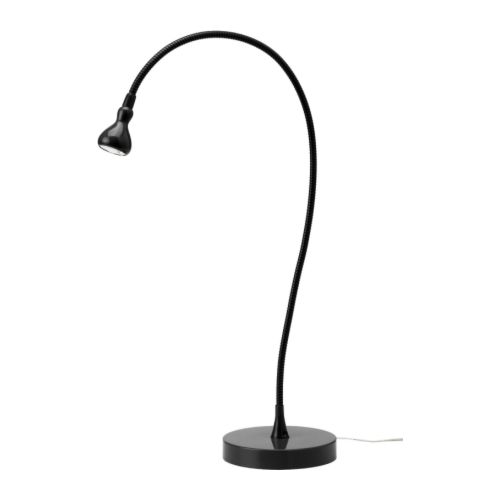
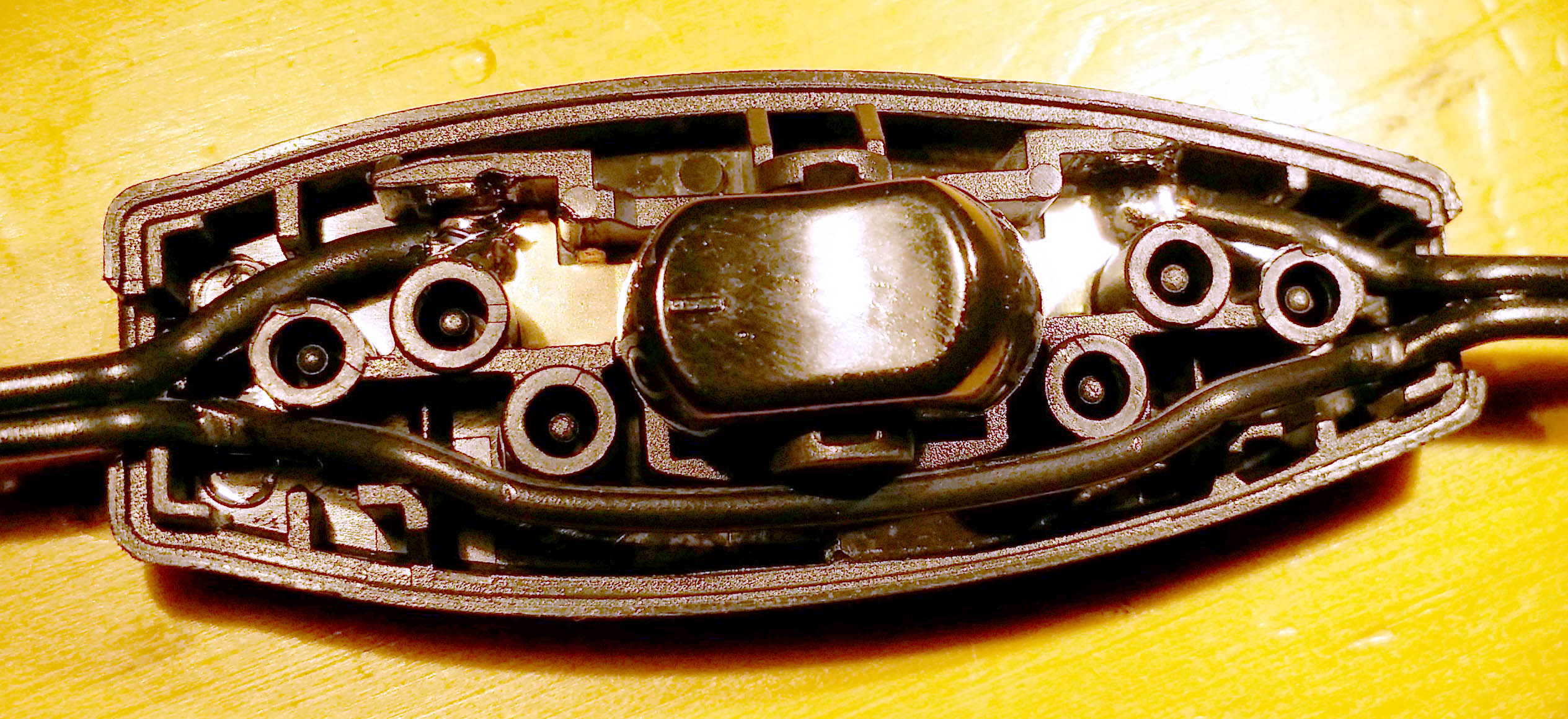
The problem appears to be mainly on the old switch design with curved sides (bottom), not the newer design (top):
20141127_210848

Instrutions

1. Open the switch

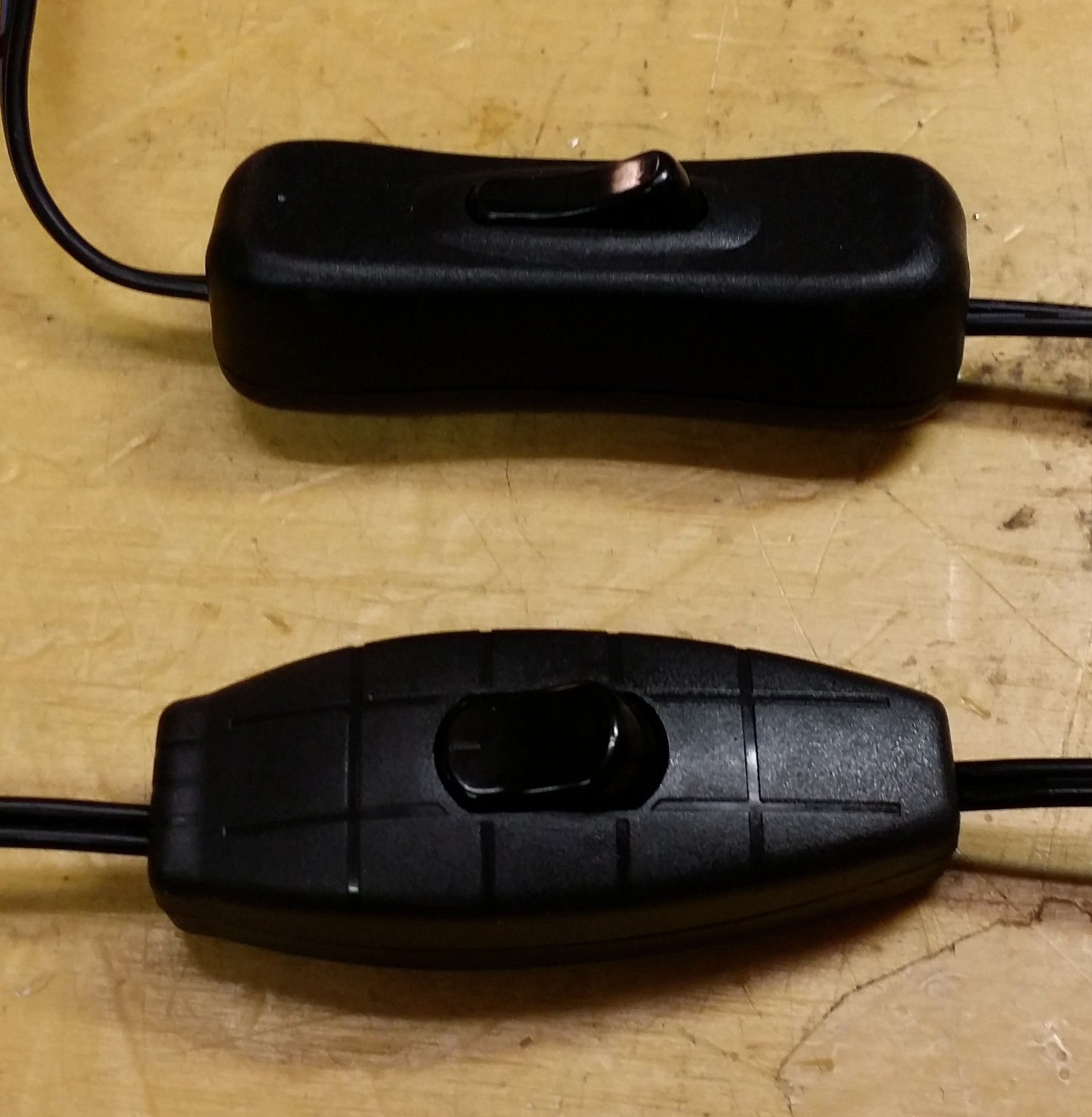
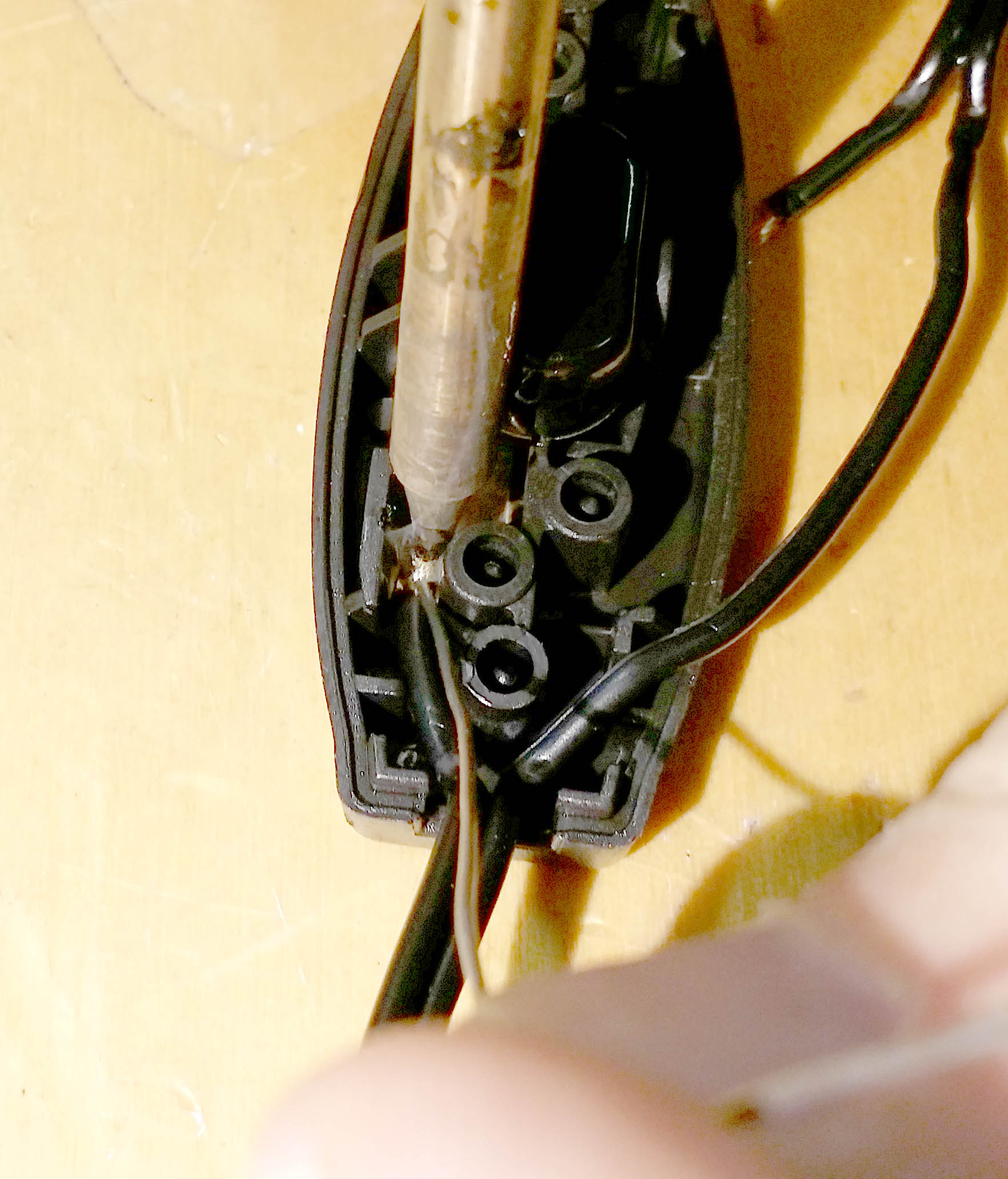
Use a pair of external snap ring pliers to open the switch. Insert them into the wire entry port and squeeze, being careful not to pinch the wire. Open one side by about 1cm, then switch to the other size to fully open the swtich. Beware of the two clear plastic strain relief pieces that may pop out from each wire entry port.

20141127_210942 20141127_211014

2. Prepare the wires

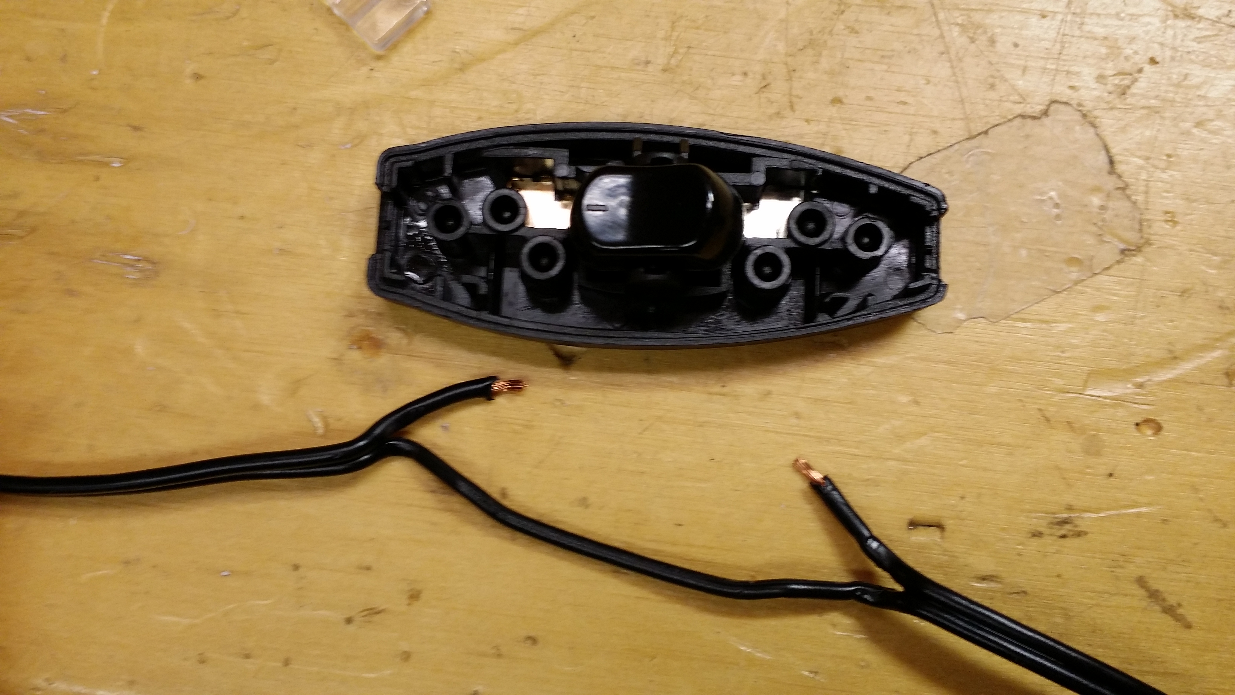
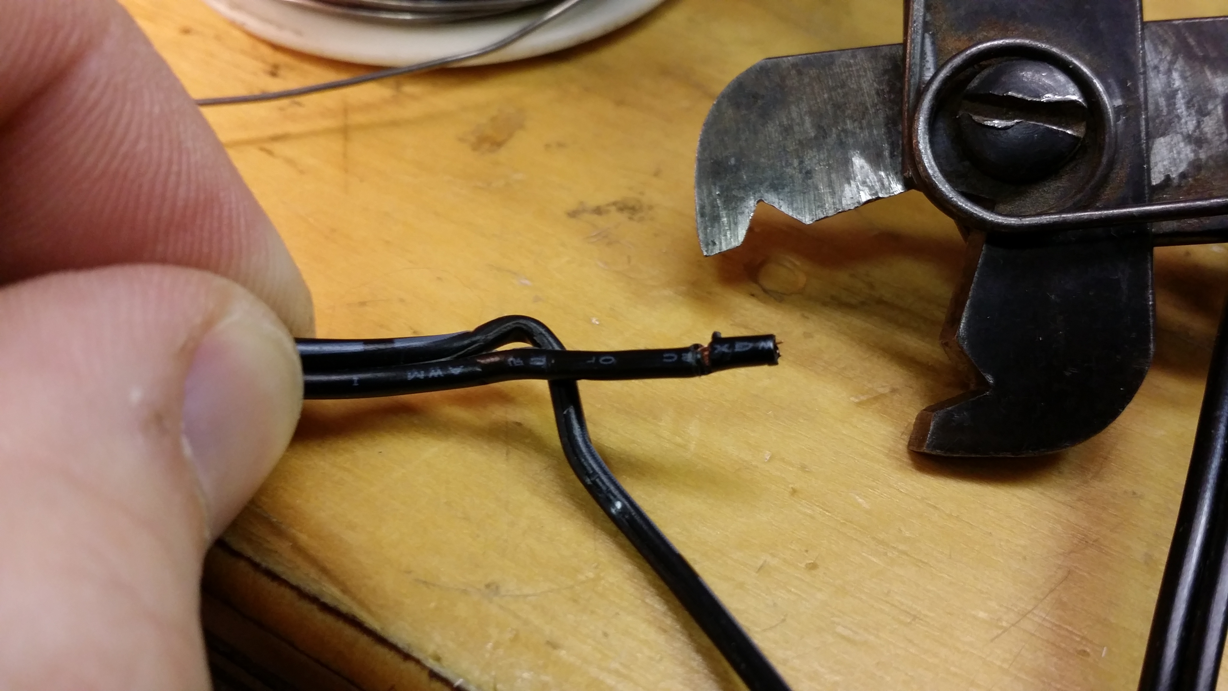
Carefully pull the wires out of the IDC contacts. Use a small screwdriver to hold the metal contacts down if needed to avoid pulling them out of the plastic. Strip the wires starting at the position where the contacts bit through the insulation.

20141127_211452 20141127_212542

3. Solder the wires in place

Use a small tip soldering iron. Place the stripped wire back in the IDC contact. You may need to push the contact open to allow it to fit.

20141127_211640_fixed

20141127_211859_fixed

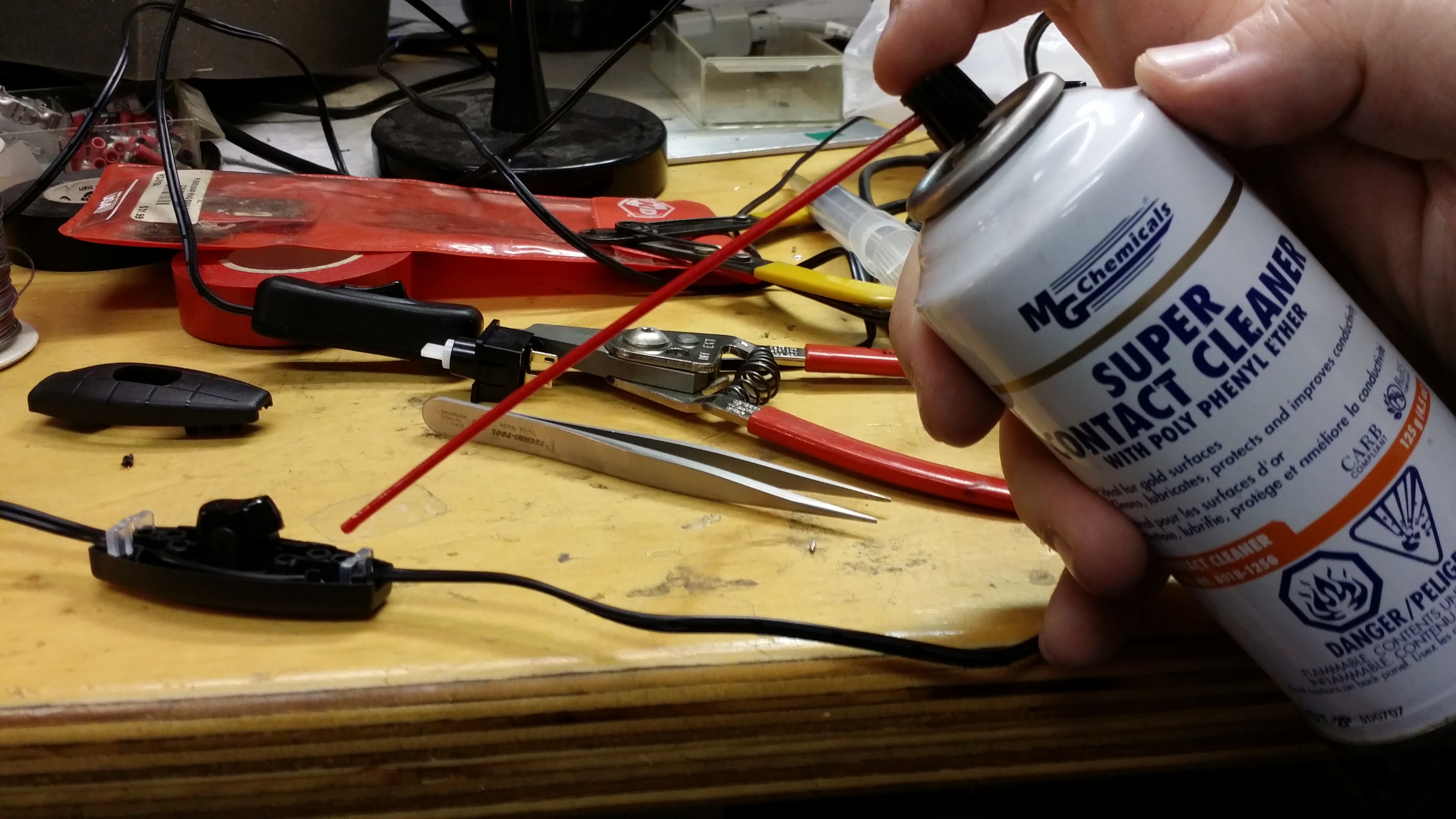
4. (Optional) apply contact protectant

Poly phenyl ether (PPE) is a super slow evaporating oil often used to protect contacts. It’s claimed to stay on for up to 40 years. This is easiest applied with a PPE-containing contact cleaner. One such product is MG Chemicals Super Contact Cleaner with PPE. Applying this may extend the life of the switch.

20141127_212036

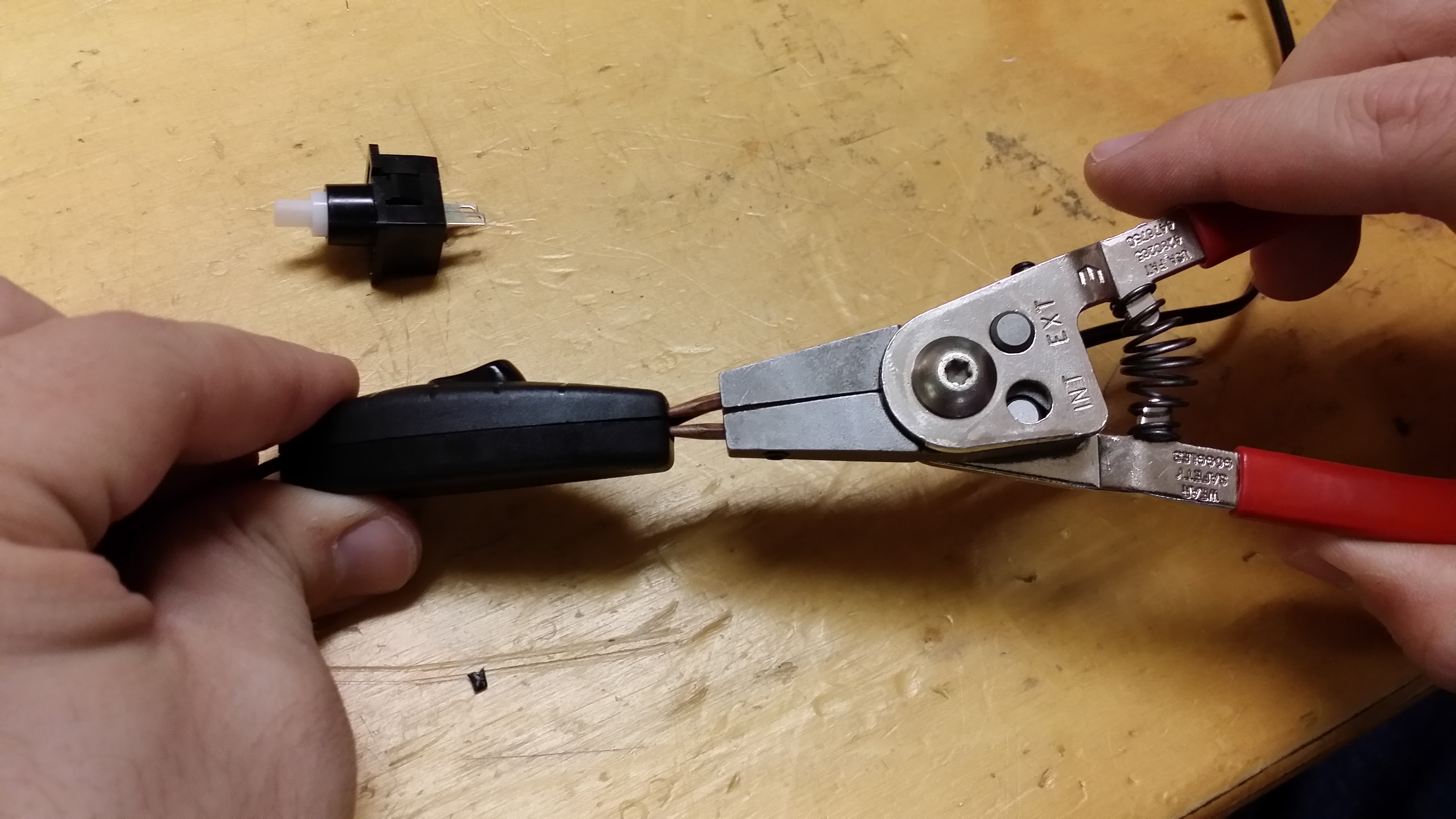
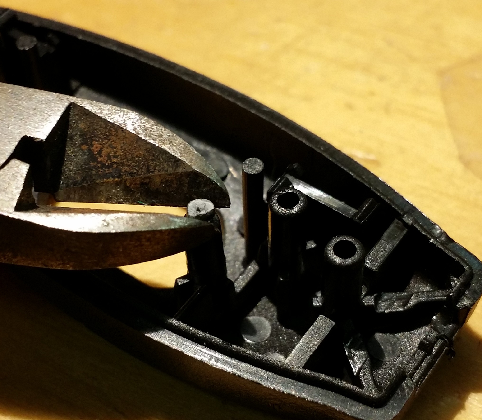
5. Cut off broken locking pins

The case is held together with friction fit pins, some of which may break off while opening the switch. Cut off any protruding nubs that are stuck on the ends of the top portion of the switch. A broken off nub is shown between the jaws of the cutter.
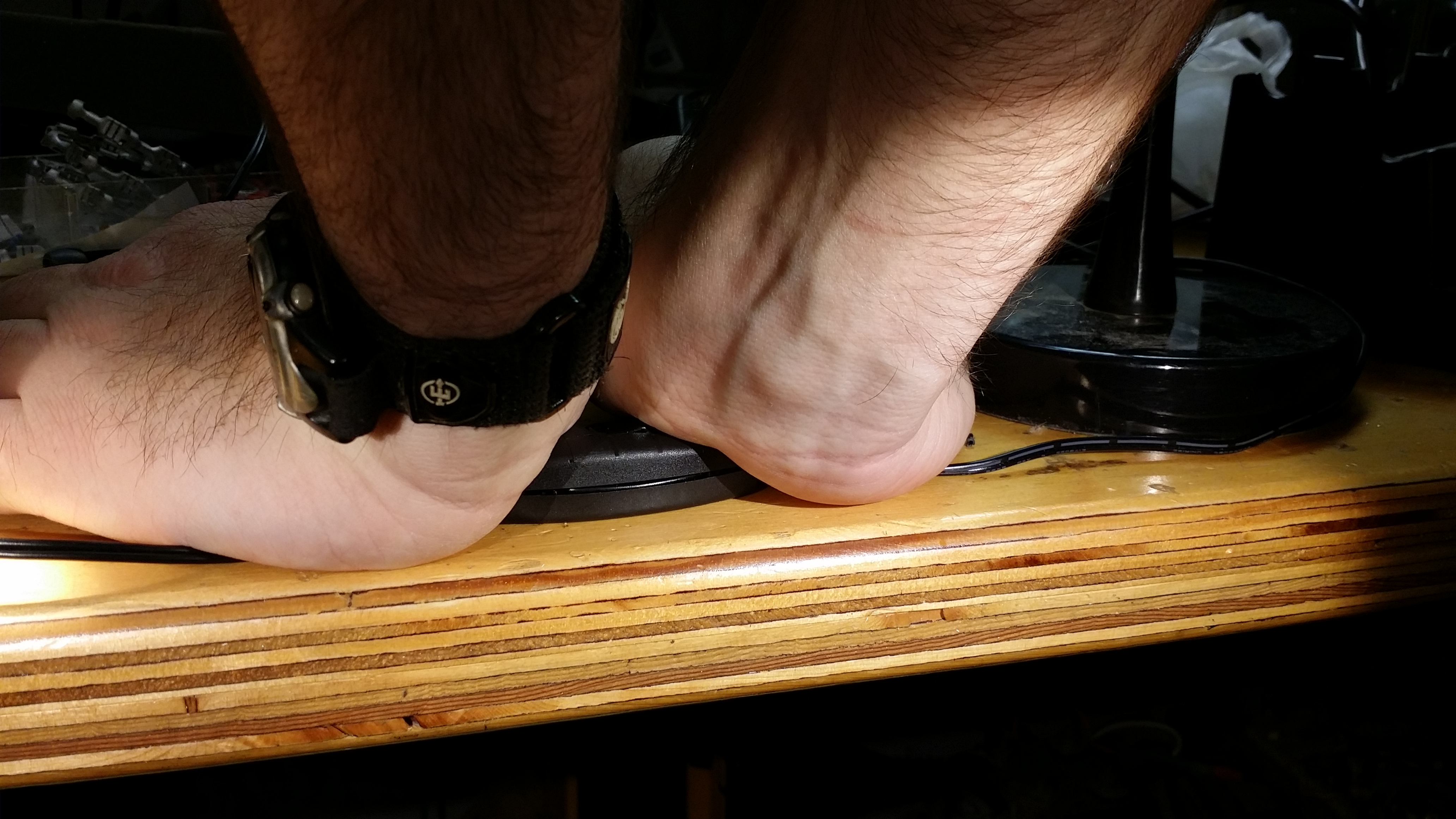
20141127_213036

6. Close the switch

Place the wires back into the switch, then put the clear plastic strain reliefs back in. Place the switch on a solid table, place one palm of each hand on each side of the switch, and press down. You’ll have to push down very hard, don’t worry about the switch breaking. You may need to put all your weight into it. You may need to use pliers if you can’t push it down hard enough. Protect the switch with a cloth for example if using pliers.

20141127_212232

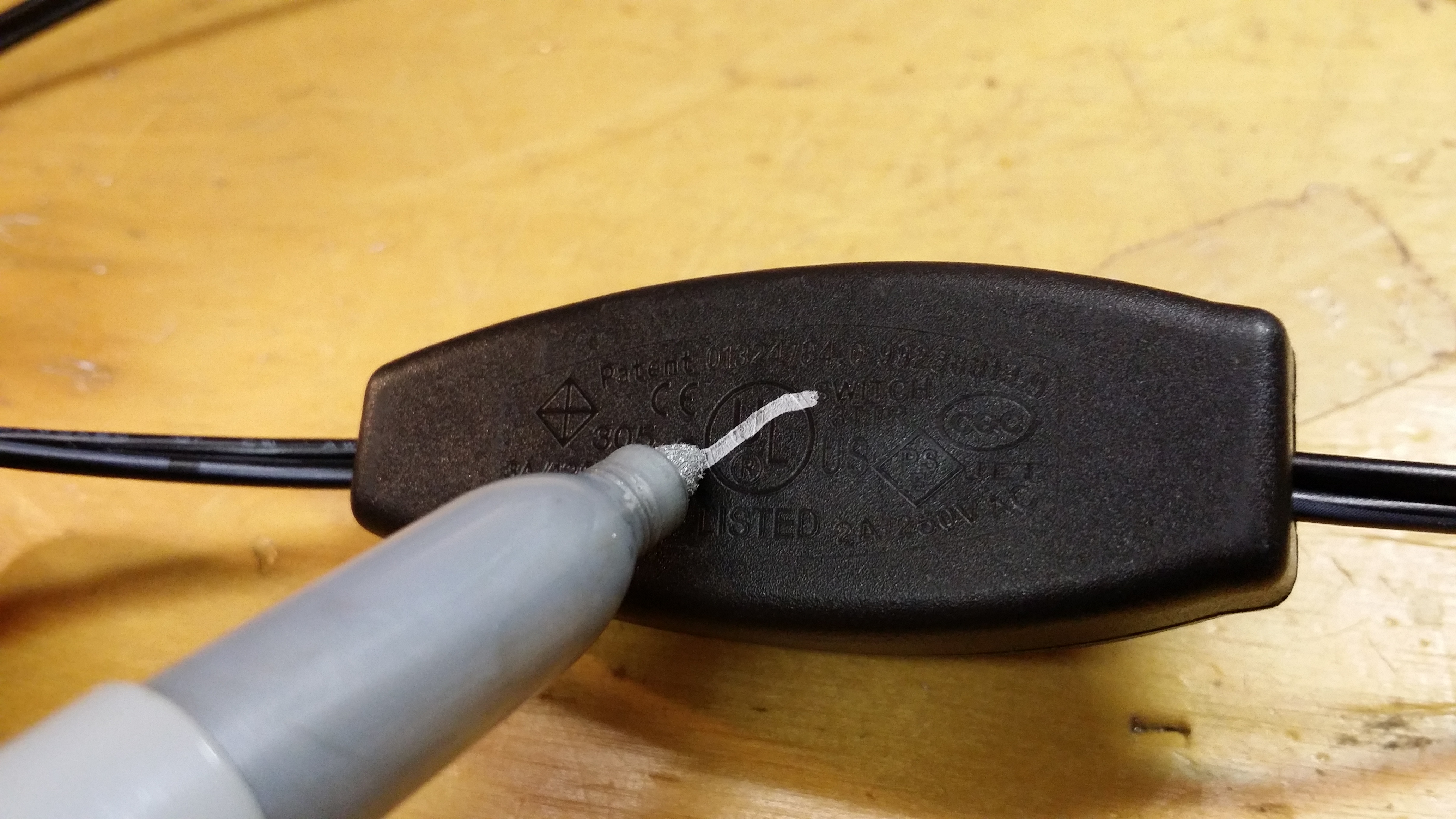
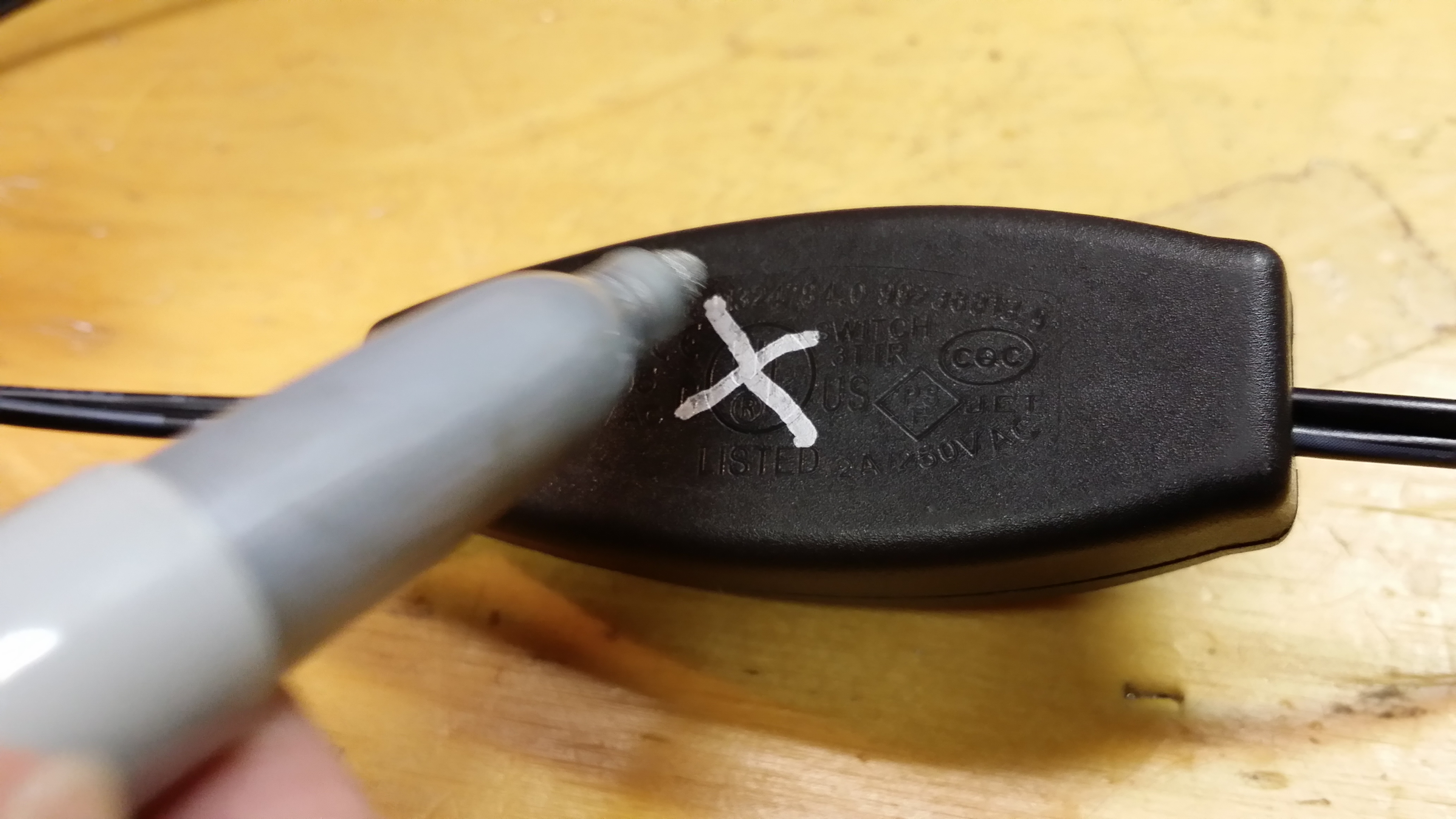
7. Do what UL should have done

This POS switch doesn’t deserve UL approval, so remedy that with a Sharpie.

20141127_212420

20141127_212431

8. Enjoy flicker-free light!

Strong 2.5kW Xenon lamp ballast teardown

This is a Strong model 62-80005 Xenon short arc lamp ballast, out of the now demolished Station Square cinemas at Metrotown. This drove lamps up to 2.5kW for the small auditoriums in the cinema. The large auditoriums ran up to 6kW lamps.

Here’s the User manual

Strong Xenon Power Supply 1-3 Phase_full

Ratings are
200-240V 1-3 phase 20.2A input
20-30VDC 50-100A output

20141029_010123

20141029_00493720141029_004814We were greeted with the lamp current control pot jammed in the output junction box by the installers.

This ballast dates from 1998, and appears to be an older design. As expected, it’s built very well, with the entire chassis being aluminum.

20141029_010014_fixed
In the above photo, 3-phase input connections are on the top right, bus capacitor precharge contactor top middle, DC output top left. On the bottom right is the EMI filter and main bus capacitor (6800uF 350V), and the bottom left contains the actual switching power supply unit.

20141029_010034
Close up of the contactor and 240-120V transformer used to run auxiliary systems in the projector. Also contains the three 5ohm 50W bus precharge resistors, which the contactor shorts out once the bus cap is charged. This avoids blowing the input breaker when turning on the power and charging up the capacitor.

20141029_010028
EMI filter, DC bus cap and input rectifier. Bus cap bleeder resistor also visible on the left.

20141029_010039
DC Output terminals

20141029_010022
Switching power supply

Schematic
Schematic from manual. It’s basically two separate paralleled full bridge converters with full wave centertapped output rectification.

20141029_030844

20141029_030929
Control section has a very “organic” layout, the designer must have really been cramming to get everything to fit.

20141029_030916

20141029_030903

20141029_031014
The output current sensor is clever, just a standard ferrite core with a hall sensor stuck in the core gap. Probably much cheaper than the commercial versions of these sensors, especially at this current rating.

20141029_030943IGBTs are IRFP350 rated 400V 16A

20141029_031510Not too bad – only a few bodge wires/components. I figure the green wire was for some safety ground purpose and and not EMI.

20141029_031545
A couple of burnt up connections on some resistors

20141029_01020320141029_031051
The EMI Filter has an absolutely dreadful layout, with long ground traces connecting to the Y caps.

20141029_031829
And all the goodies left over at the end!

Want more high current ballast goodness? Check out the video teardown of the 7kW version of this ballast. Completely different architecture!