Altium Designer has powerful 3D tools, allowing you to export a STEP model of a PCB. This is very convenient as a complete 3D model of your PCB can easily be imported into CAD programs such as Solidworks.
There is a problem when doing this with with multiple different PCBs, however. Due to file naming when Solidworks imports the STEP file, each separate PCB has a model named “Board” for example that is the model of the bare PCB. Since the assemblies for each PCB have the same part named “Board”, Solidworks will use the same bare PCB model for all the assemblies, which is clearly wrong. This problem extends to other components which have the same name such as R1, C1, etc. This import procedure applies a suffix to all components to avoid this problem, allowing successful use of multiple PCBs in one assembly.
This procedure has been tested with Altium Designer 13.1.2 and Solidworks 2014 x64 SP0.0
Important: Some of these steps like restarting Solidworks may seem odd, but they must be followed EXACTLY for this to work.
- For each PCB to be exported, create two folders, in this example the board is called YLM Board, so we create folders “YLM Board” and “YLM Board temp”
- For each PCB, export the file from Altium (save as STEP file into the temp folder). Each board STEP file must be saved into its own temp folder, in this case “YLM Board temp”. Export using the “Prefer STEP models” option in the export dialog. (Note: the Component Suffix option here isn’t used, as it doesn’t apply the suffix to some of the parts like the bare board itself)

- Open the STEP file in Solidworks, then save the Solidworks assembly in the same directory as the STEP file. A “Component documents must be saved” dialog will pop up, click Save All.
- Close Solidworks completely
- Open Solidworks again and open the assembly saved above. Do not skip this! I’m not sure why this is required, but the suffixes don’t get properly applied if you don’t do this.
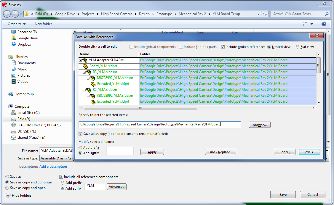
- Click File | Save As. Select “Save as copy and continue” at the bottom left of the Save As dialog, check “Include all referenced components”, and select “Add suffix”. Enter your suffix in the box (in this case “_YLM”) and click Advanced.
- In the Advanced dialog, verify that the suffix is applied to all parts except the top level assembly (in this case YLM Adapter.SLDASM). Use Browse to select the other folder you created earlier (the non-temp one, “YLM Board” in this case). This is where the final assembly will be saved. The correct configuration is shown below:
- Click Save All.
- Close the assembly and repeat for other boards
- Delete the temp folders
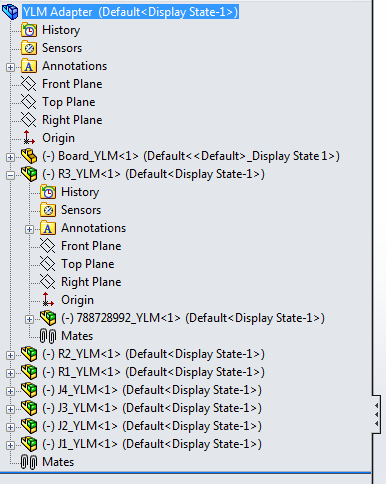
The resulting assemblies for each PCB can then be used in a single Solidworks assembly without problems. The final assembly for a single PCB is shown below, with suffixes on all components: